5/8/07
I had intended to work on the Condor today with Roy, but we attacked the transfer case on the KK instead. We first made a cardboard template, and kept re-taping and cutting it until it was a good, fit on both side.
We then cut ½” Maple plywood, fit that, and then made a second wood template for the other side. The finished templates look like this:
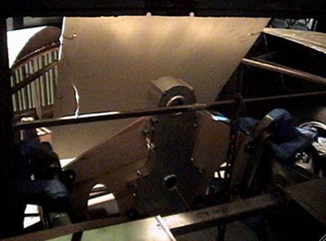
The large plywood in front is the radiator mockup. We're VERY happy to have gotten this far today. The angle of the transfer case shows as the correct 2-3 degrees forward.
We have the capability to adjust the tilt as needed with shims later. But we APPEAR to be dead on.
I cut some bracing out of the hood system to allow for some radiator mockup.
There are several challenges for placement: for instance, how about putting a couple of 10-gallon water tanks just ahead of the front tires behind the front fenders? That would add weight nicely WAY forward, as far as it can get.
If I mount the radiator at the front of the frame rails, between them, I can get about 29 wide by 19 high. With a Flex-O-Lite fan pack behind that, I have about 11 inches to the front of the transfer case. I COULD set the radiator back and make more room for a n AC condenser, trans cooler, etc. I could also mount the trans cooler to one side, or mount the condenser and cooler on the front clip and let them tilt with the sheet metal.
MANY options here.
We have also been looking at mounting a second radiator horizontally. In that I have about a 12 x 29 space behind the radiator, that could be a decent option as well.
And yet another possibility is tiling the radiator back across the top of the transfer case. Not quite as attractive as showing off the engineering, but one more option.
So there will be quite a bit of foam mock up happening this next week.
5/10/07
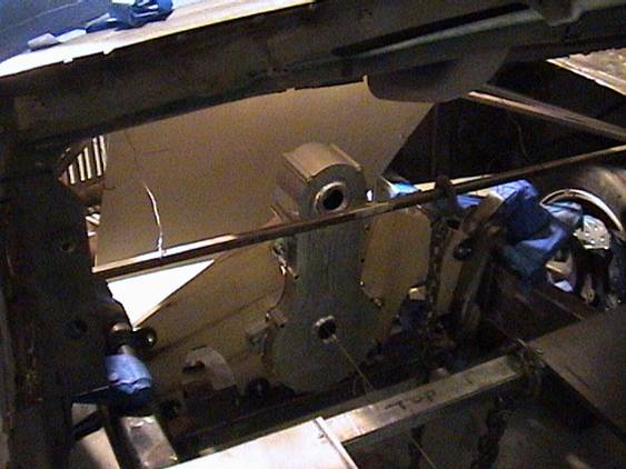
This is what Roy and I came up with today:
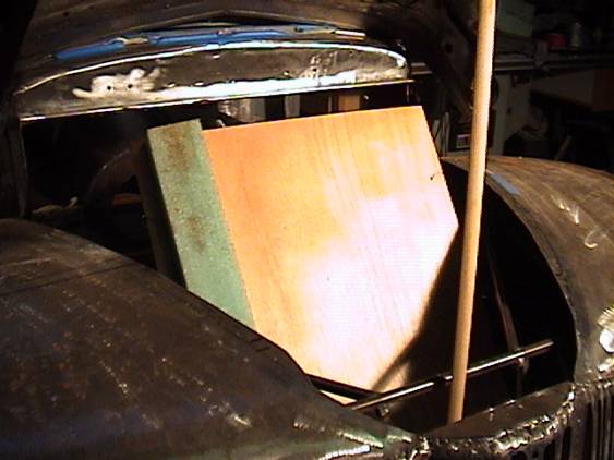
By angling the radiator, I can get a 29 x 39 unit in there. This is exactly TWICE the size of a normal unit. I can use two Flex-O-Lite twin 15” units. The trick is how to get flexible lines to the radiator. In looking at the front clip pivot, I figure I can position some water tanks there on an O-ringed pivot, and hard plumb the lines from the frame to the tank. Otherwise, we will have to come up with some flexible or large looped system, like hydraulic lines on a crane use.
We did some measuring for fuel tanks, and here is the rough mockup we did:
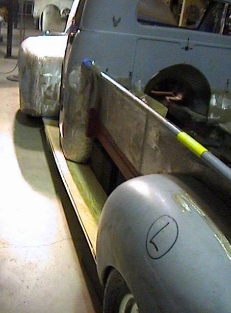
This just shows the location of a running board system, and where the fuel tanks would go (the black area between the bed and the running board). This location, and keeping them flush to the outside of the bed, will still get us over 20 gallons.
The challenge is how to mount them AND the running board. Perhaps a commonest of brackets will do that.
Roy and I also measured for batteries and water tanks. It appears there is ample room below the floor, between the driveshafts and the frame rails, to incorporate water/fuel tanks.
It looks like putting two batteries across in front of the power steering rack between the frame rails would work, adding more needed ballast up there, about 80 pounds or more.
If we do use the front water tank idea, there would be another 120# or so of forward ballast. If you look in front of the right tire, you can see some space there.
The volume of the little cab is small, but I can still fit an AC condenser about the size of the Thunderbird unit behind the grille (this would give me SERIOUS cooling, which is what I want) or crossways between the frame rails behind the radiator and in front of the transfer case. Again, some flex lines need to be made to allow that unit to tilt with the clip.
In looking at the front end tilted open, the angled radiator looks WAY cool with 4 fans on the back side. Putting them on the cab side gives us more room and allows for a larger radiator.
Roy is going to research available radiator sizes and configurations.
I will consult with Rob Anderson for some of his thoughts on pumps, tanks, etc. He says aircraft type fuel line/hydraulic line stuff. Fragola and Parker Aerospace offer some items like this. But all in all, it looks like we've made some serious design progress.
I don't want to run crazily into fabricating tanks, etc. before we know what is really working. But I am excited.
Rob pointed out some SERIOUS flaws in my thinking about the water tanks, flow, etc.
He says the extra water tanks SHOULD be on the cold side, and HIGHER than the radiator top, to allow the tank to be the air trap/outlet. He feels three independent lines from the hot side of the motor into the BOTTOM of a radiator would be ideal, with a single large outlet at the top into an expansion/storage/fill tank. Adding capacity to that tank would be advantageous. He cautions against crating an air trap in the lines from that tank to the motor. In short, avoid up and over bends in that run.
So my next move is looking for these aero bends.
5/29/07
Roy and I did some more running board fabrication today. Actually, mockup. We found that mounting the running board UNDER the body puts the 2” rolled down edge TOO close to the ground, about 4”. So we've raised the system about 2? Up on the side of the cab, leaving the rolled edge flush with the bottom of the front and rear fenders. We've also achieved a perfect 8.25” reveal below the bed front to back. This means our gas tank can be made to look even in theat space, an important consideration. I called Joe, and he concurred on our thinking. Roy and I are working on gluing up foam pieces to fit in, as there is some serious stepping and detail work to make the tanks fit up inside and look flush. We calculate about 9” depth, about 48” long, and around 9” high. Front that total we must subtract about ¾” by 48” for the indent on the outside, and another 7” x 2” x 48” for the step in of the frame rail. A gallon of gas requires 253 cubic inches. The net of all of the above, including deducting about a half inch both directions for wall thickness yields just about 10 gallons per side. We'd like more.
5/29/07
So Roy and I did some measuring of the under floor area forward of those tanks. I can get another 8-10 gallons per side adding some tanks, including making room for double 2” radiator lines to and from the motors. So it appears possible to get 35 gallons or so without too much trouble.
Now, given that we do that, there still remains stuff like: where do we put the X-members, routing of the fuel lines, joining of the 4 tanks all into one pickup (like the dually?), location of the fuel pump(s), placement of the additional cool side water tank.
We also raised the running board about 2” up on the side of the cab rockers, so as NOT to have it hanging even closer to the ground. By raising the back up the rear fender, I maintained an even line below the bed for the fuel tank reveal. This, however, cut into the volume. And these clearances to ground are without the motors, trans, and other weighty items in place. A good call to move it up.
I spoke with Montalto about raising the running board and he concurred.
Gary did not show today. He did make excellent progress yesterday. This is al moving SO slowly. But I am delighted to be bringing together a lot of nice folks doing good work.
I took the Hemi to Sal at ACT, and once done with changing out the converter and rear seal, I will have him build the KK trans.
I also spoke with Phil at MelMat foam, and he will have a 4x8x12” ready for Thursday to help us speed up mocking up the tanks. Working the 1.5# green foam is no mess, but VERY hard to trim down slightly. Easy to cut, bad to shave. And HUGELY expensive. So we'll do with some mess with white styrene and get on with it.
I intend to use an under floor master cylinder and booster to keep the firewall area clean. Gotta get that researched and ordered. I will send the xfer case and templates to Rob Moore on Thursday, and have him color them the yellow zinc chromate. I'll need to get some samples from him to match the Mark Williams pieces.
I do intend to get the Brooktronics plating kit (about 2 grand), but not quite now. Money is VERY tight, and there are other things needing doing first.
5/30/07
Roy is coming tomorrow, and will pick up a foot thick slab of white styrene foam 4 x 8. I will pull the xfer case out tomorrow (maybe), after we do some mocking up, including the under floor tanks.
Gary has been welding, but not here. He has been experimenting with the inverter/square wave unit of Brett's. They have concluded that a water-cooled “torch” (wand) and some different settings, along with REALLY cleaning the metal, will make the difference Gary is looking for in the welds. Gary is a perfectionist, and is unrelenting in his pursuit. This translates into more time. Gary also says I MUST TIG all new tack welds.
Jpe Montalto says he will visit, probably next week. I'm hoping to get him to take the bed.
5/31/07
Roy arrived with the mega hunk of foam. I showed him and Chris some techniques for cutting the stuff, using a skilsaw, sawzall, and bondo rasp.
As these pictures show, we opted for a completely different fuel tank setup. The accessory tanks we envisioned became the main and only fuel tanks. By doing some artful cutting to allow for the trans pan, we get around 40 gallons total in the two under floor tanks. Besides the nice fuel load, some other good things are: it puts about 200# forward, right under my seat, it frees the rear tank spaces for water and batteries, and puts the tanks in perhaps the safest spot on the vehicle.
Roy and I also fabbed up three foam batteries measuring 11 x 7.5 x 6. These batteries could be much longer if needed, as there are three in this plan, and situated on the right side under the bed and above the running board. The space above the left running board is a Styrofoam mockup of a water/cooling tank. As the water pump inlets/outlets are both on the left side of the motors, we figured that would be the smart route for the approximately 2” diameter hot and cold water lines.
We also noticed we could keep the radiator fixed at its near 45-degree angle, and still see pretty much everything up front with the front clip tilted open.
The thinking on right side batteries was to have more weight there to compensate for the heavy driver's side load (ME). Turns out the weights of the water tank and batteries are about the same. The usefulness of the tank on the left is clear. The wiring from the batteries to the starter, also on the left, might need to be done by going THROUGH the engine crossmember in that area. This would require opening the outside of the frame rail, welding in a sleeve to continue the “tunnel” to the left outside of the frame rail, then routing the 12-volt lead to the starter. This is probably the least of our design issues. But it is touches like this that sum in a big difference in the final product.
I made up the right side running board mock up, set it in place using foam blocks below, and found the truck was an inch low on the right. Putting 40# of air in the nearly flat RF tire helped, but it still took 2” of shimming under the RF tire to achieve near level conditions. So something is awry in the suspension adjustment in the RF.
Meanwhile, the running boards look good as positioned. The trick now is to MAKE them. I have two sets of running boards. They are not identical. So we'll see just what will work from what. It MAY be that Joe will have to fabricate them as part of his work.
The mounting scheme for the tanks involves a simple angle iron approach on the lower rail to go along the side of the tanks and under the frame rail, to be bolted to the rail. The upper rail is essentially the same, hanging on top of the frame rail and being similarly bolted down. This approach leaves the tanks completely independent of the surrounding structures.
As the pix show, I have fabbed a 2” ABS crossover pipe to demonstrate the connection of the tanks. This will represent the low point of fuel on board, and be the perfect place from which to draw. I learned this lesson the hard way on the dually dual fuel tanks.
So I feel very inspired with what was done today. We have a MUCH clearer picture of what we can and can't do, and a nice starting point for the next phase of fabrication: setting the engines, driveline, and exhaust. The routing of water lines, the cold storage tank, the presumed placement of the under floor master cylinder, the path of the steering column, and the rough ideas of the brake lines routings are all clear.
High on the list of reality checks is actually getting a master setup and getting it installed. This will settle a LOT of issues in that drive foot well and under floor area, including the firewall placement, routing of the water lines, brake lines, electrical looms, etc.
Regarding the batteries: it is not clear that we need 3, perhaps one long one would do. The issue of how many alternators should be used remains open as well. A single, small case GM unit can put out about 200 amps, and combined with a large, although long and skinny, battery might do just fine. There is some consideration of serpentine belt routings for the three motors, their three blowers, the power steering pump, the AC pump, and any possible hydraulic pump for the tilt functions.
Todd Armstrong will be here in two days to look at that situation (and some Condor details), and we'll hopefully arrive at some cool resolution, ala their late model Z06-LS7 Corvette install kit.
Someone asked me today about the reasoning behind the 3-engined approach. I noted that on the face of it the design was not the most effective power to weight ratio setup. Although it actually only fails by perhaps 400# from an ideal HUGE engine, blower, etc. setup. The engines in sum are under 1200#. That approaches the weight of an iron BBC with blower and some accessories. So perhaps this idea gives away 500# overall. At the highest levels, this is significant. But there ARE classes where the weight we'll carry will actually calc out to a KILLER Power-to-weight ratio, something on the order of 2# per horsepower. This is monstrous. A nitro dragster is doing about 3.5 HP per pound, or about 7 times better than the KiloKub. But also keep in mind that a majorly hot car like the 505 HP Z06/LS7 427 Corvette weighing 3600# is pushing 7# per HP. That is a VERY fast car. So the KK will be about 350% BETTER than that. The notion of having 1800 HP with essentially stock feeling motors is staggering. GREAT low end response, VERY drivable, nothing radically hard about the tuning, etc. I probably will end up putting a bit of camshaft in these engines just for the sound, but the setup hardly needs it.
The exhaust will also provide a rare experience for ANY car enthusiast: a TRUE 24-cylinder experience. Whereas firing 3 engines all at the same time would be undoubtedly captivating, it would just be more of the same thing. By spacing the firing order 30 degrees on each engine, and with 24 separate pulses for each two revolutions (instead of 8), this “Ferrrari-squared” engine should sound like nothing anyone has ever heard driving into Bob's!
Many of the uncertainties of the past are solidifying into realistic possibilities now. The water system looks quite doable. Ditto for the fuel, charging, and blower systems.
Gary has taken the week off from welding to weld heavily at night at home practicing different techniques to get the look just right. He's a perfectionist, and I appreciate it.
He and Brett have upgraded their system to water-cooled, a smaller torch (TIG system), and Gary is experimenting with heat, pulsing, etc. to get the beads to be really sweet and show quality. This Miller welder has ALL sorts of features that my 12-year old more basic TIG does not. I'm not ready to spend money to trade up, as I haven't ANY experience to justify getting a better tool. Perhaps later, but as noted before, there are more pressing issues to conquer.
6/3/07
Gary has apparently not gotten the new hip stuff from machinist friend Brett, so has not returned to do any more welding. I may just have to haul it over to FabTech and get on with this. I want to keep it fun and friendly (and inexpensive as possible), but time is grinding on here.
Todd from Vortech looked briefly at the truck this weekend and feels their new ZO6-LS7 Corvette kit, which is almost in production, will be the ticket for the three blowers and will keep the setup within my 30” confines.
I have done no more work with the mill or lathe as yet.
I'm really stuck until the welding is done. I DO have the fuel tanks, batteries, and water tank mocked up, but if Gary is going to weld those, I'm back in the same pickle if he can't get to them.
Roy will be returning Tuesday, and we'll do a little more mocking up, like water lines, look at some brake line routing, perhaps drop the tanks a pinch to accommodate some stuff along the top, etc.
I have emailed Rob Moore, and have it on my list to UPS the xfer case and wings to him. I will call him tomorrow and remind him of my request for some gold anodized color samples. I might also go to some local plating houses and see if they have samples. Roy also feels a truck radiator supplier might have a radiator to fill the bill. I need to talk with Rob Anderson about that as well. Rob will not be on the premises until next Saturday, at my 63 rd birthday party.
6/6/07
In GOOD news, I got a call from attorney Jim Dowling (whom I paid about $900 to file the case) in Fulton, Missouri regarding slimeball Derek Dawson, the fellow who defrauded me out of $8349 on ebay 2 years ago on my birthday and never sent the two Mercruiser motors for which I paid him. Dowling said he is going in to see the judge today and get a default judgment, as Dawson never answered the complaint, and failed to appear in court.
Dowling suggested I COULD ask for punitive damages, but I would have to appear in person. I suggested he get the default today on the principal amount, and inquire with the judge about her feelings on the punitive aspects. I'd happily spend $500 going there and back to get a few more thousand from this thief.
One thing at a time.
In welding news, or the lack thereof, Gary has said he will be down here by the weekend to commence welding. He has worked out his “chops”, and is just waiting for some additional equipment to start in on it.
And I WILL send the xfer case off today to Rob Moore, as soon as I return from a job walk.
6/10/07
Case sent.
Rob Anderson came by Saturday 6/9 for my bday party and had some comments on the cooling system design. The final word is that he WILL design it. I had spoken with Tim from Ron Davis Radiators who suggested using more core area in place of the 10-gallon water tank. Rob disagrees. So water tank it is.
There is some unclarity as to where the thermostats are to control getting the motors UP to temperature. They like to see around 210, and we really don't like that. Buy whatever the computers say, that's what we'll do.
We have the running boards temped in place, and are looking for a spanner wrench to adjust the coil heights. The RD is about 2” low at the moment. And yes, we've checked tire pressures.
There may be some A-arm adjustments needed as well. Scott's has a new wrench waiting for $20.
Now that Gary is ready to weld, he and I have noticed the mounts and crossmembers are not perfectly straight. Mind you, all pieces assembled came out to right on, but apart they look goofy. So I will have him straighten them out and we'll have to do some mods on the motor plates. Ah, the price of perfection.
Gary hopefully will get over this week, after much delay, and get this thing rolling. If not, I'll get it to Jamie at FabTech and create some progress, all good intentions notwithstanding.
Roy found me a catalog of some under floor master cylinder systems, and I need to check those and some Lokar and other kits out. That master location is critical for the length of the left fuel tank, water line routing, etc.
The approximately 48” x 6” high panel between the running board and the bottom of the bed will likely become a trim panel on both sides, removable in some fashion. The left side will be the cool water tank, and the right side may be the batteries and maybe some electronics, again with a hinged or somehow openable plate in front. Mind you, once the bed is up, these areas will be visible. But we have to offer other avenues of presentation.
I need to gather ALL the KK parts into one area, like ON the car, and find the power steering rack bolts and bushings, which I DID get some months back from Scott's. There are bunches of hardware, etc. that need inventorying, such as the power steering pump, reservoir, rack bolts, suicide hinges, etc.
The Tbird will not see a lot of progress, the Dodge is coming back from ACTR with a new trans and converter and driveshaft, so the KK should be the major focus this week. Jorge, John, and Mike will be working in Santa Paula at sister Jacki's house for several days, so only Chris (should he show up) and Roy on Tuesday and Thursday will be available to help.
Gotta get those motors in and properly located to move to the couplers, exhaust, water line routing, electrical, etc.
I also saw the MOST bitchin' coil over valve covers on the new prototype Camaro with little hatches to cover the coils. They looked majorly cool. There may be no need in my case as my valve cover cover will be about 7: long to enhance the 24-cylinder look.
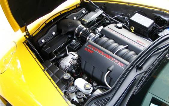
This is KIND OF the setup, but the Camaro had polished valve covers and intake. But this is the general look of the neater looking coils/cover. I also saw some neat Weiand polished aluminum manifolds for around $600. But that may have to be later. Gotta get this setup actually running first.
7/7/07
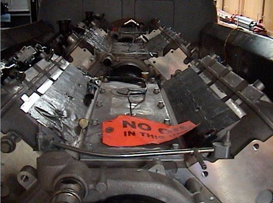
Adam Stokes, a new addition, has been working for a couple of days. He was referred several times by Nick of Hamrick's. The kid is motivated, gets RIGHT to it, and has aptitude. I have put him to work on some job stuff, and on the KK as time permits. He and I got the 3 engines back in the truck, and are now working to get them re-aligned. They WERE aligned previously, but in our ardor to make things SO perfect, we changed the relationships of the crossmembers and mounts, and now I have to do it ALL again. I get to revisit my methods, and invent new ways to check alignments, etc.
Gary has yet to finish the welding. I just went ahead and put a wood block under the rear motor, and I think I'm pretty close with it right now.
I think we'll have them pretty much aligned tomorrow. There is a question of center axis alignment. The #3 engine (closest to the cab), had to be moved to the left (driver's side) at its rear about 1.25”. The front (toward the front of the car, but the rear of that engine) mount tweaked it out of alignment when the bolts were tightened. So we went with a longer bolt through the mount of the passenger side, and we will have to mill a shim to correct that. The #3 engine also had a bit of a right side tilt, and we corrected that with just a very minor redrill of the other front mounting hole.
I did find some of the stuff mentioned above, like the power steering rack bolts, pump, steering knuckle, column drop, etc. Still more stuff to gather, but having the motors off the floor makes it easier.
I talked with Morgan at AirMec (now just an employee there), and he has not gotten a commitment from the new owners yet for the AC system.
Joe Montalto dropped by. I asked him to put in writing my nearly $50K credit. He has not done so as yet.
7/8/07
Adam and I had a long day on the KK today. We are REALLY having to do some tweaking to get the motors straight and aligned. The problem now is that all the mounts are made, so we're struggling with things that can't be moved, etc. We have the front (#3) motor FINALLY in its REAL position. The rear (#1) motor looks essentially there. So now the middle (#2) motor needs to go left about 3/8” and up about ¼”. This will require slotting the forward mount plate sideway and slightly up, and notching the right rear mount on that motor to allow it to move over. The spacing beneath the mount legs in the back will be handled with shim of some sort.
Mind you, ALL of this alignment was done before we stated welding up and straightening the crossmembers and mounts.
Adam has turned out to be just the right guy to help on this. Mechanically adept, willing to work, and no whining.
7/9/07
Randy decided to spend the day with me, and in the afternoon we looked at the engines' alignment. I asked what he saw, and he concurred the center engine was over to the right a bit. He, however, thought it needed only rotating UP on the right to make it work. Turns out he was correct about the rotation, but the whole engine had to go to the left about 3/8”. I tried some different spacing on the rear mounts of the rear motor, but it was best as it was. I also cheated the rear point over slightly for a better alignment. The motors are way good now, certainly plenty good enough for a one-piece rocker cover (cover) for all three engines.
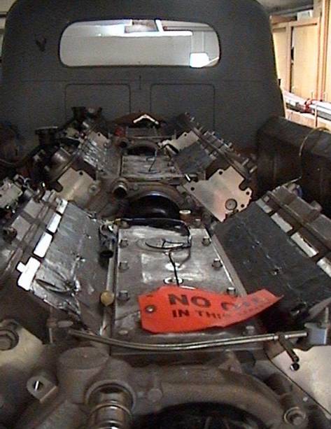
However, the alignment along the bed rail is now not perfect. The rear of the bed will need to go up perhaps a half inch to line up perfectly. This should not be horribly difficult, but will require some cutting and welding of the pivot attachment to the bed framing. That will be a Montalto thing. Joe will also be addressing an unwanted downward curve, particularly on the left bedside rail, once he gets into the bodywork. It takes a HUGE amount of massaging (aka doing it two or three times or more) to make this all look effortless and perfect in the end.
Gary came over tonight and did some welding. He had to run to a family crisis, and will return tomorrow. Meanwhile, I need to make some mount spacers from ¼” steel, so that he can weld up the mount “feet” and keep everything aligned.