9/24/06
Joe has got the front clip as a unit and tilting. There remain some challenges with that, as the following will elucidate.
9/28/06
Joe had to redo the pivot point to get the front to clear the tires. By extending the pivot point to the center of the pivot beam, rather than in the frame rails above. A perfect hinge point was achieved. A benefit is that the 4x4 member which acts as the pivot and holds the entire front together, now clears the bottom of the frame, allowing a radiator to sit directly above it. Of course, we can gain another 7” in height by moving the radiator back about 7 inches. This would provide for a 27 wide by 19 high standard Mustang size unit, or more than one of them. The space in front of the radiator(s) can be condenser, trans cooler, and possibly the Vortech “brick” blower intercoolers if we go that route. There are some serious questions about using multiple radiators, how to duct them separately, etc. But for now, we have some real dimensions with which to play. I can not install anything yet, as the temporary framing inside the hood and fender assembly prevent that. But, we can mock stuff up, and start exploring the relationships available for water and fuel tanks, etc.
Here are pix of the revised pivot system.
10/2/06
We're still having a tire interference problem. There are several solutions possible: remake the front suspension crossmember lower in the frame rails to essentially raise the frame and body panels relative to the tires. Short of that we might widen the fenders, radius the wheel wells, or flare the fenders a bit. The wheel well openings are below the rim, and I don't care for that extreme a look. So, some tweaking is required at this juncture.
10/14/06
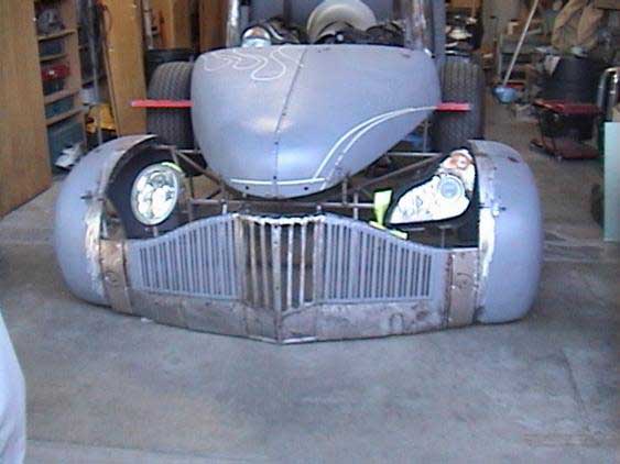
Note the picture below which shows the entire front clip repositioned about 3” higher. This puts it about at the height we had it on the street picture, which I have included below with a before and after shot for a reality check on what we've done to this truck.
and the incredible after:
Here are 7 of the 9 lights we tried:
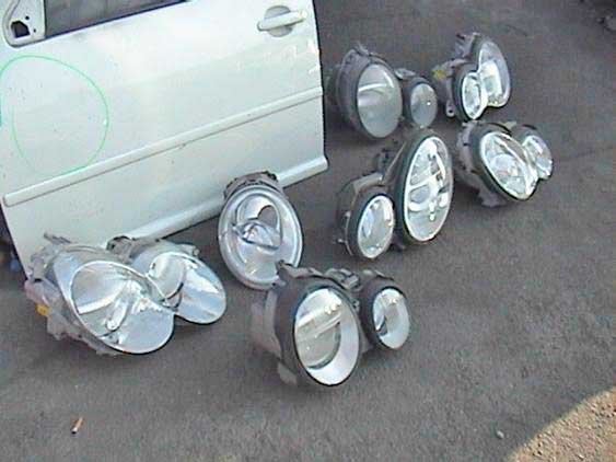
And here is a two-light test:
And here is the final selection:
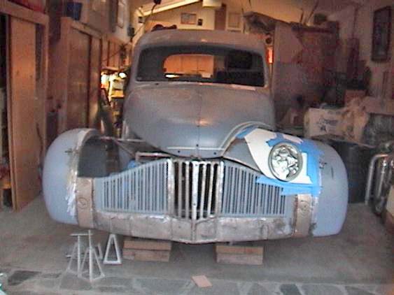
I measured the width of the rear fenders at 72”, and the front at 80”. As noted before, we have widened the front of the car about 8”. What you're seeing here is with the car about 12” HIGHER than it will actually ride. This is a MEAN, Panther-like looking machine. The VW bug headlight was just right for the “look” of the car. The other lights were way cool, hi-tech, but NOT that sweet combo of nostalgia and modern. We feel this light hits it right on.
I have also mocked in a BMW 325 driver's side power seat from the same source as the lights: Greg at Hi-tech Auto Salvage. He specializes in high-end cars: BMW, MB, etc. He also is VERY trusting, and allowed me to take the 9 headlights home for a trial fit with nothing more than my business card in his hand. I returned and John Jarnagin and I sorted through dozens of seats at will measuring and looking. Again, Greg just let us take it home for a trial fit, no money exchanged as yet. This guy will be THE source for anything salvage we ever want in the future. The BMW seat is the narrowest seat I can find so far at about 20-1/2” at the bolsters. The track width is also the narrowest at around 17-1/2”. There MAY be some other smaller seat out there, but this feels right at the minimum width for my butt. We might relocate the power controls for the seat to the console, and with a little work gain and inch or so on the left side. We're struggling with making room in the center for the trans cooler lines, which means pushing the seat more to the left door panel. Depending on how the power window system fits, we MIGHT be able to recess the door panel slightly. We're working with fractions of an inch in this area.
I have also determined that the legroom required for at least my legs means we need to move the firewall forward about 2-3”. This is not a major deal, as we have removed the firewall altogether at this point.
Headroom with the 325 seat is fine for me. However, for a tall fellow like Randy at 6-3, it might be a little tight. No problem. If he wants to drive the truck for extended periods he can buy his own seat.
I need to purchase the power brake booster, pedal, and gas pedal assembly. I will be using an electronic throttle control, meaning a wire, from the accelerator. So just as we did with the dually/Duramax swap, we will get a 5-volt rheostat pedal assembly with only a wire and no other linkage. That makes it way easier. The brakes will be the old-fashioned system with power booster and stainless lines.
I found a VERY good source for many things electronic, called Electric-Life.com
This site offers beautifully finished stainless suicide door hinges and all manners of wipers, power windows, etc. Of great interest is their line of linear actuators. These are electric power rams using a motor and screw gear to push 200# as far as 12” We will use these instead of the more cumbersome hydraulic or air systems (no lines, pumps, etc.). They are also very cool-looking:
They offer these units in 4”, 6”, 8”, and the above-pictured 12” stroke models. We will do some measuring and see just what will be needed for the front clip and the rear bed.
On the exhaust front, I tried out a pair of Aero Turbine 20” long 304 stainless mufflers with 4” inlets and outlets on the funnycar. Here is a cutaway view of the unit:
 Still loud. But they offer great promise for the KK as they are compact, large pipe size (up to 5” in and out), and using say 6 of them would sound insane, and look cool. I'll obviously need to do MAJOR measuring before we settle on anything, but they look like the coolest thing so far.
I believe my version has a plate inside for slightly more baffling, much like a Super-Trap motorcycle muffler.
Anyway, 4 or 6 of these would be quite stunning. Or hey, how about just two for MAJOR sound?
On the more majorly mechanical end, I'm hoping to get Rob Moore his template by Tuesday, allowing him to fabricate the mounting portion of the unit. The template is made and ready to mail. As the Mark Williams rear is a beautiful gold color, I'm inclined to have Rob's work similarly colored, and carry that same color into the motor mounts. That way the entire drivetrain will have a co-ordinated appearance, and not appear to be a bunch of put-together discrete parts.
Joe and his dad got the trans tunnel partially done. Here is a shot of the bellhousing cover. From the front of this piece forward it will be tighter to the transmission. I have a turbo 400/Powerglide trans shield, and we might incorporate that into the tunnel, or at least make room for it.
10/17/06
Papa Joe has gotten the front half of the trans cover done. Next is the upper driveshaft housing to the transfer case/firewall area. As we have discovered we need to move the firewall forward over 4 inches, and we do not yet have the transfer case here nor mounted, we really can't fab that portion, nor the firewall. Joe and Pop are concentrating on the front fenders, filling in the VERY wide sections between the fenders and the hood, and slowly removing the inner structure which now interferes with any mockup of radiator placement, etc. Tomorrow we will determine what length of stroke we need on the electric rams, and some possible tentative placements and geometry. Joe intends to have the fenders pretty much together by Friday.
In BIG news, I picked up the cranks and balancers from Ollie today. Roy will commence on reinstalling them Thursday.
I intend to do some 3-engine mockup next week, and start to look at some exhaust possibilities. One of which is that Fast Intentions MAY step up on the headers for some SEMA exposure next year. Danny will let me know sometime down the road. Meanwhile, he will consult my website to get a sense of the project. Joe removed a plastic cover on the right side of the driver's seat, providing a precious 1/2” more of room.
I need to get the power window kits, brake master and pedal, wiper system, and the AC ordered and here to allow for some placement decisions.
I have updated Jeff Willerth (producer) of the KK progress. By his silence I sense this just isn't the right time for him to get it as a project. So we just keep slogging along. Happily, I have about $50,000 of sponsorship so far between Al & Ed's AutoSound and Vortech Superchargers. If Fast Intentions comes aboard, that could mean $6000 or more of value.
Placing the before and after pix on the website was a great reminder for those of us working the project just how far it has come.
10/24/06
Ran into Jay Leno this afternoon at AutoBooks in Burbank, while gathering knowledge and manuals for reassembling the LS-1 engines. Jay was kind enough to call his chief mechanic on the spot and put me on the line to ask Bernard some questions about torqueing the bolts. Seems GM now uses a small torque figure plus a number of degrees to turn the bolt AFTER the initial torque setting. So rather than say 65# on a main cap, you torque a bolt to 15#, then rotate it 76 degrees. I'm serious about this. Then there is the issue of reusing the bolts. As these motors have zero running time so far, we are gong to reuse them. I will nonetheless check with ARP about how THEY would do the motor with their fasteners. Each bolt on the main cap array uses a different setting. Utterly new info here.
Joe did not make it yesterday or today, notwithstanding he said he would get here today. He is with a cold it appears.
I have ordered (6) Electric-Life rams, (4) of the 6” stroke, and (2) of the 12” stroke. Joe had asked for 4” units, but they are not available for quite some time to come. I personally don't think the sorties will work anyway. I can return the unneeded units. I have also ordered their universal electric window kit.
I will have to look to Lokar or others for the wiper motors.
And, I have a question for Mark Williams: can I use a hydro-booster brake system with his calipers? Hydraulic boosting gives more pressure, and some calipers don't like that. I should also send the calipers and mounting plates back to Bret for proper sizing.
I need to contact Greg at Hi-Tech Wrecking regarding the seats and headlights, as I have not paid him anything as yet.
I also need to contact Rob Moore and see where we are on the much-delayed transfer case.
10/25/06
Saw Greg at Hi-Tech. We were unable to find a matching seat, and we were asked to cease rummaging through their parts. So we'll bring back our trial seat, and let them do the searching.
Talked with Rob Moore and he is sending the empty case to arrive here Friday 10/27/06, and we'll start our trial fitting from there. Rob also confirmed he is ready to build the adapter, motor mounts, and mounting plates as needed. So my plan for next week is to set the motors in the chassis, temp up some mounts, do some alignment and measuring, and mock up some broomstick driveshafts, etc. to see where we are.
Regarding the engine bolts, we are told we must discard the rod and main bolts after one tightening. So I'm ordering 3 sets of ARP bolts for all three engines, rods and mains. This is about a thousand bucks.
Joe, Cesar, and Joe Sr are busy working away on the fender fillers, trans tunnel, and misc grinding.
I have run out of time today and did not talk with Lokar nor Mark Williams.
11/2/06
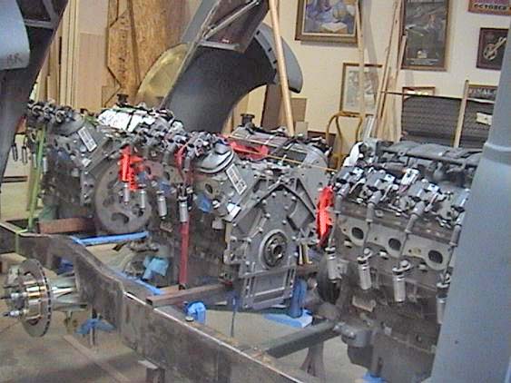
Today I spent ALL day working on the engines. We (Dick, Roy, Brett, then Joe, Cesar and Sr.) worked on the mockup of the three engines.
I discovered a little problem in that the front of the pickup bed curves down slightly near the front, so maintaining a perfect alignment front-to-back along that rail was troublesome. After moving the engines perhaps a dozen times in and out, up and down, many times left and right, we got them essentially perfectly aligned, using a string line pulled through the groove just below the valve covers. Mind you, using CV joints does not require such precision, but I have other reasons. One is that I want to mount full-length 7' long valve cover covers (yes, correctly stated), and having the engines aligned will make that much easier.
I want the visual from the side and rear to be perfect, and we have achieved that. Here it is with the bed up.
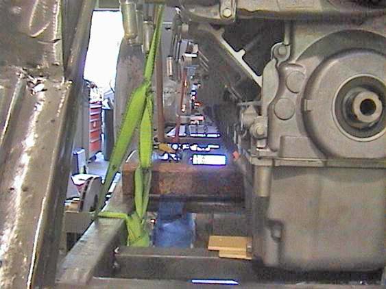
Now for making mounts. As we looked at it and conjured up designs, it occurred to me that we might just use 2x2 crossmembers as we are for temping them in, and just put tabs up to the lower bolts holes front and back. A HUGE benefit from this approach will be liberating space alongside each motor for the exhaust. We also need to make room for water tubes for hot and cold water. Notice the view from the left rear of the “cavity” we're triyng to create alongside the engines:
Another issue is the height of the transfer case. Rob made the drop at 10.5", only because I said the first unit had that dimension. It turns out we could have gone much closer. But no mind, this is what we've got. It appears we'll have to LOWER it behind the front crossmember to line it up with the trans output shaft. We CAN lift it up, and have an upward angle there, requiring u-joints or CV joints and not allowing for the use of a straight funnycar coupling system.
We will be mocking up the output shaft of the 4L80-E tomorrow using wood dowels, and we'll need to adjust the pinion angle on the rear end to match, about three degrees downward. Once accomplished, we'll know what angle to tip the transfer case, and what angle we need for the center support bearing on the driveshaft. It really does not matter if we go up and down, as long as we maintain everything in the same plane. That's the theory at this point, anyway.
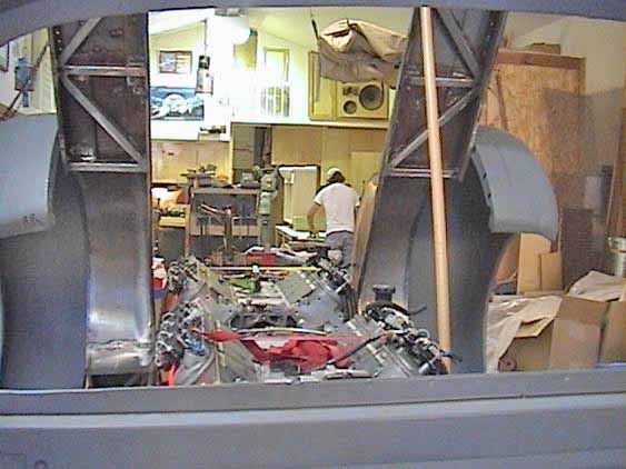
Today was massively satisfying. The view from the rear of the car is just astonishing, seeing those three engines appearing as one. Really cool.
11/5/06
Spoke with George Barris at Bob's Friday night. He was quite intrigued with the KK. He noted he had done both a twin-motor and a 4-engined (Pontiacs) project. On the quad motor he used two pairs of engines in line, connected with clutches, and then two transmissions connected to one power gathering box, and then to a rear end.
I am quite concerned about the timing of the motors, so for now I'll stay with rigid connections. Barris said he would look at my website to view the project.
Joe is scheduled to return tomorrow, Monday 11/3/03 to continue. Last week was only a few days for Joe.
I need to do some research on the motor mounts, but Joe and I feel straight-down mounts to crossmembers will do the trick. I'll ask other experts.
11/8/06
The crossmember/mount situation continues to evolve, as with most of this project. We might go with round tubing as Scott did for the shock mounts at the rear, and put tabs off these. We're still working on this one.
A cool view is through the back window of the cab at the three motors:
11/25/06
Joe has taken most of Thanksgiving week off, to return 11/27/06. Today, Saturday, I finally got a few hours in and made up a new temporary adjustable tie rod so I can roll the car around. I also welded in two crossmembers. These are just tacked for now. I have two other people who can do the fine tig-welding we want to see at a later date. For now, I made up one motor mount for the flywheel end of the center motor. This mount can go on either side of the rear of the motor. It is on the car's left side, motor's right (remember, these motors are facing to the rear). Anyway, I made it out of 1/4” steel, to see just how close I really am with the crossmember and bolt pattern. I'll refine this rough piece until we have a good pattern, then make 4 nice pieces for motors one and two. The third motor, closest to the cab, will have the trans bolted to it, and will require a full ring under the bellhousing. Same pattern on the actual mount portion, but a full bellhousing bolt pattern will be required. I COULD make all three the same, but that's just a LOT of metal. I also have to consult with Sal at ACT regarding the spacing for the torque converter.
I will put in some time again tomorrow, and perhaps get a little further on the other crossmembers.
11/26/06
Spent a lot of time organizing the HORRIBLE tools disarray, all done by others, of course. Also put some time n the crossmember/mount situation. I added a third hole to my steel mount, and all seems to remain lined up, including swapping it side to side. So my pattern appears good, and with some detailing on the actual hole locations, I can move along with a styling look at the mount itself. It is a functional piece, but I'd like to swoop it and have it follow the engine profile contours for a cleaner look. Gotta make sure that keeps enough meat in it. I'm looking around for some 1/4” steel tab material. I'll just cut some out of my 1/4” plate, tack it in, and see how it looks from there. Drilling through both tabs and the engine mount should be interesting, as I don't have a lot of room. A right angle drill, perhaps the air unit, will be the method of choice. I need to insure that the motors REALLY are in their proper positions, and that will require Joe setting the final bed position. My camera has just malfunctioned on the memory card, although the video portion now is good. Little challenges abound.
I am officially over a year now n the project, using the time I took it to Scott's as the real beginning of doing something. Justin/Scott Padfield has NOT delivered the power rack bolts and heim joints as requested now a couple of months ago. He also did not return my call of earlier in the week. He's VERY good about calling me 4 times a day when I owe him money.
12/13/06
I had Randy go by and get the Padfield parts, in person. They were just sitting in bins. Silly lack of customer awareness andn service on Justin's part.
I actually find I need more of those fittings. Precisely, I need the track bar with end, see photo below, as a secondary motor mount on all three engines, both sides near the front. Roy feels they would work nicely, and I see they will look great.
Joe and Papa Joe and Cesar and Jay have been doing wonderful things on the front end. They just don't show at first look. They have literally taken the front end sheet metal apart several dozen times, remaking pieces, reshaping, refitting. Many, many times.
When done it will all look easy and like it should have ended up that way the first time, rather than being metamorphisized through three dozen iterations.
Beautiful, magical, thoughtful, dogged, talented effort without reserve. Check out the changes:
I am ordering ends for the electric rams, and some suicide door hinge kits. I already have the power window kits, but no glass.
And, the windshield is almost certainly going to be a butted-glass setup, as we eliminated the chrome strip on the hood today, as part of narrowing it at the rear for better fit.
I discovered an interesting “highlight” we may use later: I striped off an area per my friend Billy Record's insistence on laying out some scallops on the fenders. I painted around the tape, and when I pulled off the masking tape, the cross-hatched bright metal revealed a fascinating accent. We might use it for pinstriping around paint or openings, and other areas, and just clear-coat the raw steel.
It's all just a continuum of making it up as we go.
12/16/06
Chris Loudon has come on board as our video editor. He is an audio-video post-production editor in the movie business, and has worked on some big-time pictures.
We have transferred all the video and still files to a Mac PowerBook, and a backup hard drive. Chris has familiarized himself with the I-Movie editing tools, and after a few days of messing, is making some progress on the footage.
Chris wants to get a LOT more footage of different stuff, like interviews, jokes, my other cars, etc. to round out the kind of material needed for a series or one-hour episode.
On the chassis front, Roy has made up some more mounting plate templates for different situations on different motors.
The continuing challenge is to make up motor mounts which minimize intrusion into the “exhaust corridor” along the sides of the motors. Obviously, no “commercial” mounting plate or anything else available is appropriate to our specific needs, hence we have to invent these parts. If we did these all day every day and had a full staff doing nothing but this, we could knock this stuff out quickly. As we are really just enthusiasts making this up as we go, it takes a little longer. Next time will go MUCH faster. I am presuming some people out there will want us to build more or different projects once the KK gets out there.
We are using some cantilevered designs on the front and rear of the #1 (rearmost) motor. The exhaust may exit next to this engine, and clearing a path down to the underside of the frame is the goal here.
As an aside, and speaking of clearing a path, I have put quite a bit of stuff on ebay, and a half dozen items sold, so some things are moving out of the garage, and that's a good thing.
I spoke with my webmaster, Derek, and told him we want to put a “links” page on the site for our growing list of sponsors, the latest of which is Electric-Life.com. These fine folks are supplying the power window kits, suicide door hardware, and electric rams for the hood tilting.
So far we have:
Al & Ed's Sound Systems ( www. al - eds .com/hotcars )
Vortech Superchargers ( www. vortechsuperchargers .com )
Modern Paint/Glasirit paint materials ( www.ellispaint.com )
McGruder's Vintage Parts for paint work and body ( www.mcgruders vintageparts .com )
ACT torque converters and transmissions ( www.actperformance.com )
Electric-Life products ( www.electric-life.com )
We're looking for people and companies who want some serious exposure when this hits the magazines and shows. The larger areas of opportunity are headers, plating, polishing, anodizing, powder-coating and upholstery.
We are going to commission the running boards next week. We already have the originals, but they are too short. So we need to fabricate new ones about 8' long. Along with that we need to create new mounting systems, as we have lowered the whole package about 8” down over the frame, so original mounting schemes are of no use.
Joe and I have discussed making the fuel tanks straddle the frame rails between the cab and the rear wheels, much like Chevy trucks of the 70's and 80's. While not the ultimate in safety, outboard tanks on this vehicle may be our only real choice. Joe and I also talked about putting the tanks under the floorboards.
For now, the plan starting at the front of the chassis going to the rear is:
Trans cooler
Condenser
Radiator
Water tanks on each side of the transfer case and tight to the firewall
Water lines to the motors
Fuel tanks
Exhaust floating through the frame/engine “corridors” to the rear
Of course we have LOTS of other items to package and route such as batteries, computers, AC lines heater hoses, AC unit under the dash, etc.
I am working with Morgan at Airmec in Chatsworth on the AC system for my 58 Impala, and for some sponsorship on the KK heater/AC using a CLASSIC AIR SYSTEM.
Airmec Auto Air 10217 Canoga Ave. Chatsworth, CA USA Phones: 888-440-7077, 818-341-7077 Fax: 818-341-7532 Fax: 818-341-7532
Morgan's email is: fvm01@aol.com
And his website is: www.airpartsonline.com
I noted some time back that I had spoken with Danny at Fast Intentions, who did my Condor headers, about the KK exhaust. I will contact him Monday and see if I can bring him on board.
12/18/06
Mike from WAAG Powder Coating came by, and expressed interest in being involved in the truck. We discussed different systems and finishes, and he is researching some colors for me. He can also CNC plasma-cut our motor plates out of 6061 aluminum. This will be cheaper and faster than a full CNC- machined piece, requiring only that we do the hand finishing on the holes and edges. Probably a good way to go on the first run of motor plates. Plasma is not as clean as water-jet, but not as expensive, either. Mike can do our other brackets as well.
I'll need Joe Ziola for the TIG-welding once those pieces are made.
3/4/07
Little has been done by Joe Montalto since the last update.
I went out to his place, did the HUGE wiring job to get his shop/garage operating, putting in several weeks of back-breaking labor, and now I have a $50K credit toward more work on the KiloKub. Of course, now Joe won't come down here to work on it!
I won't allow it to be moved in any event until I'm done making the mounts. Sadly, John Santiago, the mil-spec welder who was to fab them, died VERY prematurely at age 56. So Roy and I have continued on, along with help from John Jarnagin.
John and I have spent weeks grinding, welding, and fitting ¼” steel rear-mounting plates. Motors #2 and #3 use the same plate,, The rearmost engine, #1, uses a slightly shorter (about 2”) and slightly wider (about 3/8”) plate, as its mounting requires side and bottom plates to make the mount cantilever to the rear of the truck, to mount on the existing shock crossmember.
The side mounts are going to be copies of the Panhard bar, using the same components. I already have the ends, have some gold-colored Heim joints on order, and will get the adjuster bars in stainless steel once we mount the two ends on two of the three motors.
The #1 engine will get a different “front” mount system, as we have to make room for the exhaust to dump downward at that point, and I can't afford the space to put another crossmember in there.
I have had two plates rough cut by WAAG powder coating. Mike there has a CNC plasma cutter. I am having him cut some of the lower mounting plates for engines #2 and #3, and will pick up those critical pieces tomorrow.
He will also be cutting the #3 engine plate using my massively massaged template.
I'll post some pix this week of this system, once installed.