3/13/06
As I am out of money, Scott has ceased working on the frame. He is essentially done boxing and pinching it, but has not commenced installing the front and rear suspension and rear end. Mark Williams will be shipping the axles this direction probably tomorrow, for a likely arrival at Scott’s later this week. I am intending to go up there to assist Randy in procuring a used compressor from Justin on Wednesday. I will also borrow Manuel’s trailer at Anacapa and pick up the body pieces from Santos to clear his shop. I have NO clue where to store them down here. I have been working in the garage cleaning up a bit, organizing, tossing some small stuff. But I need HUGE room. I’ll perhaps hang the body from the hoist, the rest, who knows?I spoke with Mark Williams himself twice today regarding the linking of the three motors. I ran Bret/Randy’s idea of the plates/axle stubs/collar idea. He felt that going to CV joints might be a better way, allowing for quieter operation and allowing for lubrication (inside a dust boot as well).
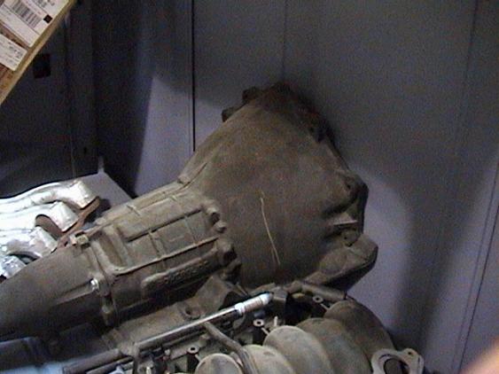
Here is the mockup trans (using a Powerglide) to show the approximate location in the driver’s compartment:
The Ford 203 four-wheel drive transfer case is intended to be positioned approximately like this:
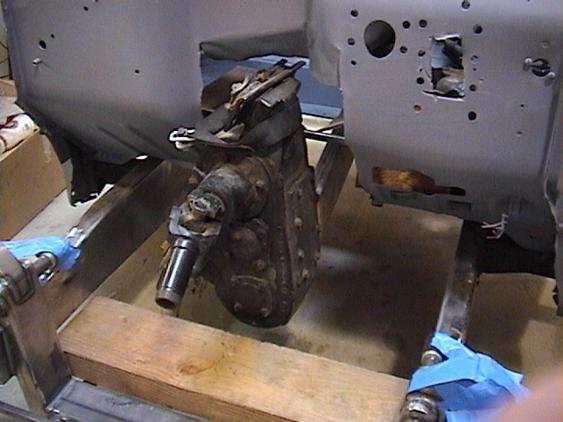
The front yoke, shown hanging here, will not be used. Jim Kirkwood is SUPPOSED to make a block-off plate to cover the front end of the through-shaft. This unit is HUGELY heavy, over 200 pounds! And for weight distribution, that is a good thing.
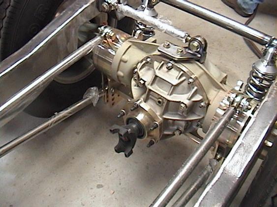
The Mark Williams rear looks like this now that it is finally in the chassis:
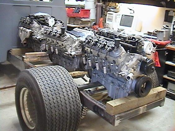
You can see why I want to be able to have people see this. To that end, Joe Montalto and I had a lengthy session today fiddling with ideas and the layout. We put all 6 exhaust manifolds on, in a few configurations. We also reviewed his renderings of the body mods. At first glance they appear very minor. In fact, what he has in mind, as shown by the rendering below, is slicing a 6” strip out of the beltline of the body. This will preserve the roof dimensions and the body accents, but will dramatically drop the overall line down. We will have to modify the grille as that is a full-height thing, and we won't have full height.
Joe, his assistant Jay, John Helbrecht, and I discussed several ideas for cooling, exhaust, mounting, and marketing the car. Helbrecht shot some video and is looking to pull in sponsors. Joe said he might get some people to step up as well. Joe and I will be working a trade deal for my contracting services in exchange for his bodywork. I like the fact that he is not only good, but is interested and wants to get started immediately. He can do a lot here in my garage.
Brett and I will be putting the front clip on the truck tomorrow and Friday, and Joe will then have some dimensions from which to work. We discussed flipping up the bed and front clip for display and servicing purposes, and he suggested using Tbird convertible top mechanisms, pump, and hydraulic lines.
Regarding the cooling, it occurred to me we could use the hollow frame rails for a LOT of water circulation. There is a fabulous car built in
Again, Rob Anderson at Vortech will be THE guy to tell me the REAL physics and # regarding this approach. That would provide a LOT of heat sink, and simplify the plumbing around the motors.
That's what this brainstorming is about.
Joe suggested just making some mounts dead center on each side of each engine. There are 6 bolt bosses on each side, and if we make a large plate, we can use two legs down from each mount at about 45 degrees down to the frame rails straddling around the header outputs. This would be VERY strong, VERY stable, and fairly simple. There are some decisions needed using this approach:
For instance, do we make it all able to unbolt, or weld the “engine stands” to the frame? Welding in the structures would provide a very easy way to drop engines in and out, as the mounting pads would be fixed, very much like stock motor mounts. We COULD put sleeves through the frame, and run bolts through, while preserving the water tightness of the frame, to allow the mounts to be chromed or coated. I'll be doing some mockup with lighter tubing and we'll see how it goes. The subframe concept appears to be dead at this point as it appears it would put major metal in the way of needed room for exhaust, plumbing, etc.
Joe also suggested using a transmission crossmember with a rubber mount. The engines and mounts will provide a lot of stiffness to the frame, and certainly another crossmember will only help the frame. The issue is whether it puts the trans at risk from frame twist. In my FC, we do not use a trans mount, as the tube frame twists too much and breaks the bellhousing when a rear mount is attached.
I will contact Rob Moore at NitroDriveline tomorrow and get those CV's coming.
Another issue right now is how far back the rear engine sits. Ideally, I'd like to move it forward to be about centered over the MW rear. This would greatly assist weight distribution. But, it will be what it is. I need to get the engine connections completed to solidify the spacing. I can certainly make them farther apart, and it appears I can get them really close. I just need those CV's and plates done to know for sure.
I also need to get moving on the front balancers and getting the cranks double-keywayed, and the balancers broached in like kind.
So really very exciting stuff today. Lotsa movement, lots of possibilities, and some real momentum. Joe will be giving me a budget shortly, and that will make or break what will happen next.
4/29/06
Got a note from Wes at Nebraska Chassis, the fellow who was in the running for the rear end fabrication. His unit would have been great as well. Nice guy, and I appreciate his interest in the project.
I ordered the (4) CV joints from Rob Moore today. He and I talked abut fabricating the plates, obtaining centerlines and indicators for proper concentricity, and making up the 28-spline approximately 8” long axles to connect the motors. He can do all of that.
I called Hawaii Racing, and they had only one SFI-rated balancer in stock, and that unit has only thee holes in the face. I feel I need six, so I put a call into ATI Performance, but they were just closing up late Friday after 5:30 PM and asked that they call me back on Monday. It may be that I'll end up with a front hub, not a balancer. They should know what will work best.
Getting the 30-degree offset between motors as noted above should prove interesting. I don't think there is an adjustable way to dial that in, as each spline of the connecting axles represents 12.8 degrees of rotation. Now a 36-spline unit would do the trick, but the C/V's aren't supplied that way. We'll probably just have to be very precise when indicating the bolt holes for proper timing. Rob should have no problem doing this.
It is clear how we can center the adapter plates on the back of the cranks, as there is an approximately 1.5” diameter boss there on which to seat. I asked Rob how we would indicate the adapter plates on the balancer faces, as well as the C/V joints themselves, and Rob suggested machining about .200” recesses as needed to seat them. This says to me we're talking about 3/4” thick adapter plates of major strength steel here. That's why these guys get the big bucks. So it is appearing quite doable.
Rob also felt I was going to be stuck with the 8” spacing, as opposed to getting it down to say 4” or so. It IS feasible to tighten it up, and it would be nice if I could move the rearmost engine forward another 8”. I actually need about 14” of forward movement to get it centered over the axle. But that will not be the make or break thing at this point. Maybe I'll need to put water in the front tires to keep the front end down! This exercise in creativity and innovation obviously should have some “how did they do that” aspects, and some evidence of thoughtfulness in design. In short, we gotta make this cool. But I'm not looking to become a slave to esoterica here. I want to DRIVE this thing! Doing it right, smart, and strong should be impressive on its own.
5/1/06
Joe Montalto is coming in the morning to begin work n the body. We're gong to attempt to assemble the front end on the truck, look for some relationships and how the sectioning of the body will affect the hood line, fenders, etc. Joe intends to weld it all together, leading the seams. This is the highest level of workmanship possible. Some may argue welding and grinding and following with bondo is the way. Leading should be good for about 30 years or so.
5/4/06
Joe did show, two days in a row, and we got a LOT done.
We had discussed sectioning the body about 6” right through the belt line of the car. This notion preserves a lot of the original details and lines of the body, but dramatically alters the stance and proportions. In addition, lowering the elevation of the cowl and top of the hood at the bottom of the front window offers possibilities for swooping the front end as no other approach can.
Having said that, we might be going for an 8” section.
For now, Joe has mocked up the front end, and found the front track width with the big tires and wide rims requires the fenders to move 4” off the body to clear. That's just fine, as that widens and flattens the look from the front, and adds another unseen but effective “something is better and different, but just what happened here” to the design. Chip Foose said his aim is the make alterations which are not readily apparent, but have you looking and admiring the improved lines and proportions.
That said, here are some pix of the temped up front.
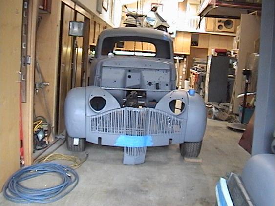
The first thing you probably notice is the center grille section hanging down. In original form, that grille stuck UP that amount, forming an inverted TEE shape. The tall shark nose hood design, much like a 40 Ford, mandated that kind of grille.
What you then see is that the cowl and body can definitely use coming DOWN. If you look at the cowl, then look down about 6-8” at the rib in the firewall, that rib will be the new top of the hood line. Now that immediately opens up being able to swoop the hood down to meet the grille line n the center, giving a MUCH more swoopy and modern look.
In addition, the right headlight opening:
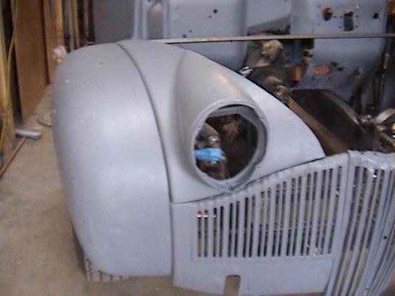
Shown here with its stock enclosure is certainly nice, but how about eliminating the “dormer” and making the area more flulsh and Mercedes-like with tilted back lenses:
This has more of a Willys/Mercedes look.
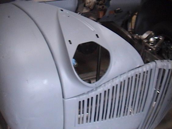
Here is how the left front opening looks:
This I think shows the degree to which we can really round the nose of the car and make it dramatically more pleasing, removing all the tallness and clunkiness from the design, yet preserving a very unique look.
Here is Joe:
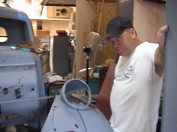
with the left headlight enclosure coming off the fender.
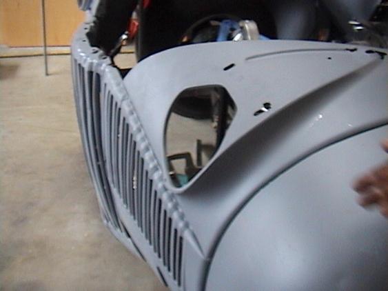
Here is another view of the mocked up front:
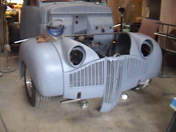
So the lower portion of the grille will be cut off, the hood will come down from the lower firewall line and tuck in, and the headlight surrounds you see in this shot will be gone.
This design just shot my excellent 5-core dually radiator, waiting in the wings, right in the head, as it is now too tall for this application.
Joe intends to return this Monday 5/10/06 to start welding up the hood and fenders into one piece. I think I will take the grille out for chroming, so we have to provide some mounting for that. Joe or someone will have the happy task of working those bars into perfect alignment.
I am utterly THRILLED to see this rapid progress on the body. I have had to make a many tens of thousand of dollars commitment to Joe to do this, and he is taking my serious financial and emotional commitment seriously.
MOUNTINGS, ETC.
I have moved the motors around a few times, but it appear snow that the rear motor being completely behind the rear end is necessary. I haven't received the CV joints as yet. I did contact ATI and Fluidampr and evaluated both products. It appears the Fluidampr is slightly less costly and will do the job nicely for around $800.
This figure inludes two Fluidamprs, with double broaching (two keyways cut) in each. The mounting holes available for my drive connections are only three, and are blind holes. Rob Moore had noted he could cut reliefs in his plates as needed. The Fluidampr is about 6.35” in diameter, and the inner diameter somewhat less. As the CV joints are around 4.5” in diameter, there will need to be careful thought given on just how this plate is constructed. I see a 3/4” piece critically relieved to fit inside the inner bore of the balancer, and thick enough to take bolting of the CV with no interference with the Fluidampr itself.
In other drivetrain news (or lack of it) I have heard nothing from Jim Kirkwood, transfer case master, despite my nearly dozen inquiries. I will have to move on to others who know this unit, and get some fabrication started on blocking off the front yoke, checking the ability to run this thing essentially upside down, perhaps putting some sight glasses and or drain plugs in, getting the 203 unit cosmetically restored, and THEN bolting the thing into the chassis.
I might have mentioned it before, but this unit DOES have a low gear provision, should I have any need to granny-gear the whole setup in say heavy traffic…
![]()